Hey guys, hope you are doing good. Few days back I discussed about the choice between a distributed deployment and a simple one. Near the end I said, if you want to do a distributed deployment then it is better that we use a virtual load balancer like NSX. So this blog is all about configuring NSX load balancer for a distributed deployment for vRA 7.1.
For the purpose of this blog I will use NSX 6.2, vSphere 6.0 U2, vCenter 6.0 U2 and vRA 7.1 (well I wanted to test out 7.1 J).
I will not cover NSX environment deployment and Load Balancer configuration for NSX as there are enough blogs already available for this. I will simply start with the Load Balancer.
As you may know that Load balancer can be configured as “One Arm Mode” or “Inline Mode”. Since I already have another Distributed Router configured in my lab so I am using “One Arm Mode”. It is simpler and I wanted to load balance in the same network segment.
This is an important reason for choosing the One Arm Mode.
Provided below are the network details of the configuration:
Hostname | IP Address | Purpose |
iaas-web1.lab.local | 10.134.91.178 | IaaS Web Windows 1 |
iaas-web2.lab.local | 10.134.91.179 | IaaS Web Windows 2 |
iaas-mgr1.lab.local | 10.134.91.180 | IaaS Manager Service Windows 1 |
iaas-mgr2.lab.local | 10.134.91.181 | IaaS Manager Service Windows 2 |
vra1.lab.local | 10.134.91.182 | VRA Appliance 1 |
vra2.lab.local | 10.134.91.183 | VRA Appliance 2 |
| | | |
Load Balancer IP | IP Address | Purpose |
vra.lab.local | 10.134.91.201 | vRA VIP |
iaas-web.lab.local | 10.134.91.202 | IaaS Web VIP |
iaas-mgr.lab.local | 10.134.91.203 | IaaS Mgr VIP |
Here I am not following a full distributed deployment model. Since this is a lab environment so I am not creating separate servers for DEM and Agent. I will install these two roles in the available servers. But will do these in distributed way i.e, there will be two DEM’s (DEM1 and DEM2) and two Agents of the same configuration. Anyways that is part of vRA implementation. I want to cover only the Load Balancer configuration here.
So here it goes….
Open the NSX Configuration page and create a NSX Edge appliance with the following configuration for the UPLINK.
 |
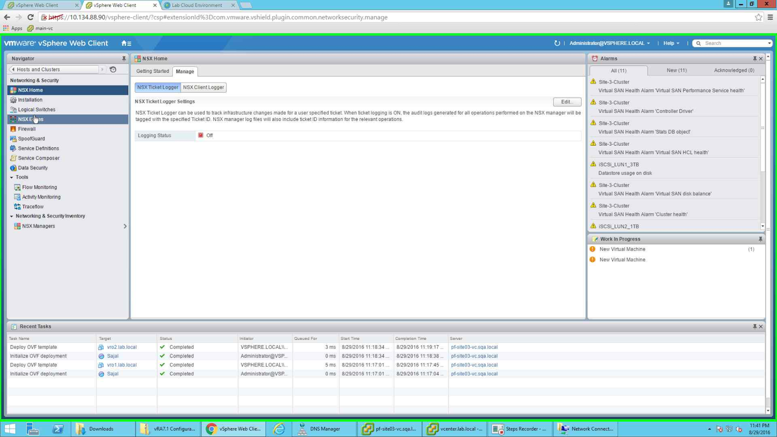
| Open the NSX Edge configuration page |
I have already created an Edge Appliance by the name "Sajal-LAB-LB".
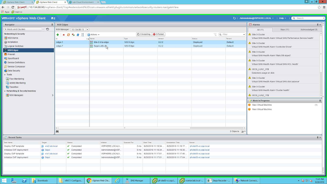 |
| Create one NSX Edge Appliance |
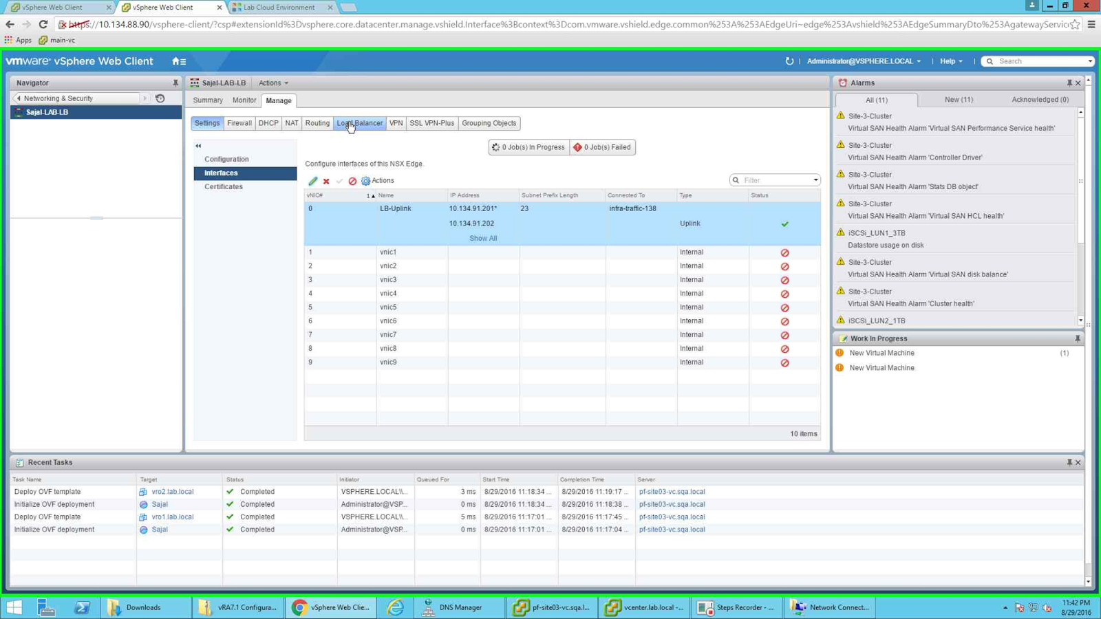
Note the uplink configuration. I have connected the uplink to the portgroup where my servers will be. Also note, the primary IP is the VIP of vRA, since I will use the same appliance for load balancing all the components so I have added all the rest of the VIP's as secondary IP address of the UPLINK. This is ok with my lab environment. If you want you can create separate Edge Appliances in LB mode for each of them separately as well. You can configure this while creating the LB or at a later time by double clicking on the Edge Appliance and going to Mange --> Interfaces page and clicking on Edit button after selecting the interface.
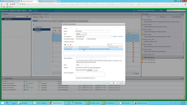 |
| Uplink configuration |
After the configuration, the Interface should look like the following picture. Since this is a One-Arm LB configuration, so no other interfaces are configured.
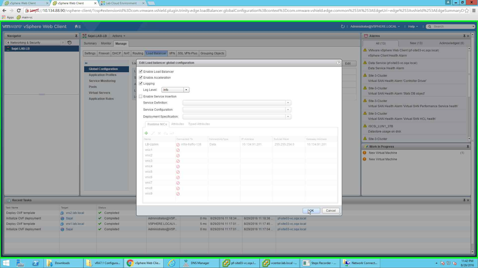
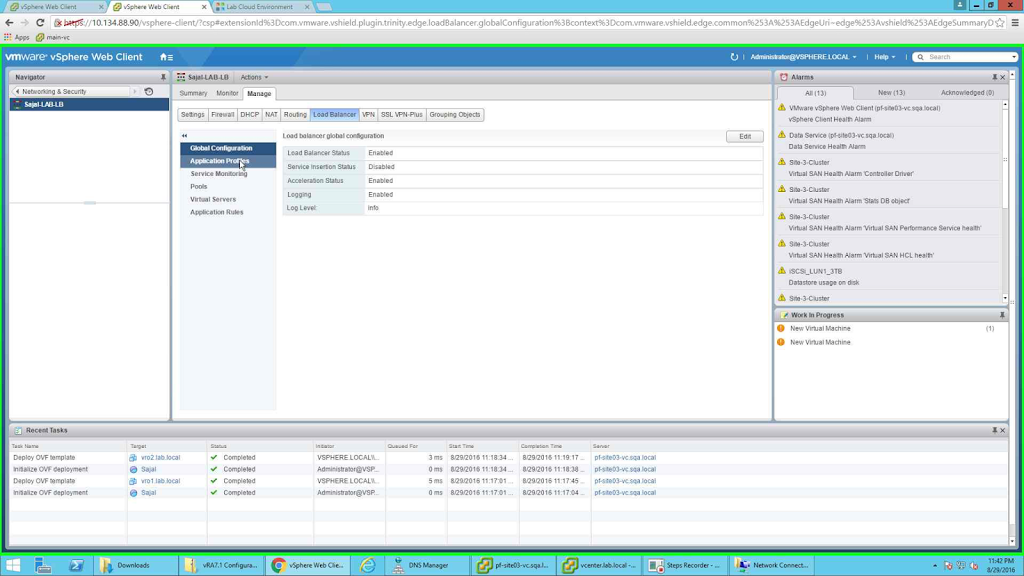
Next, go to "Load Balancer" tab and enable Load Balancing by selecting EDIT button in the "Global Configuration" tab (left side) and making necessary changes.
 |
| Enabling Load Balancer service |
Next we need to create Application Profiles. For this we need to select "Application Profiles" from the left side button of the Load Balancer tab.
 |
| Application Services |
Since I am configuring LB for 3 components namely vRA Appliance, IaaS Web and IaaS Manager servers, so I will create 3 application profiles. The names of the profiles are:
- IaaS-Web
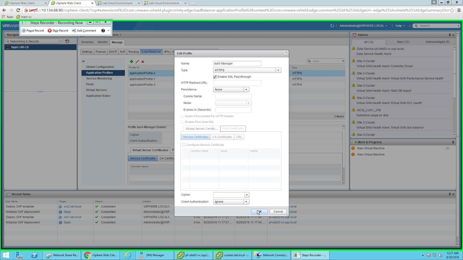
- IaaS-Manager
- vRealize Automation VA Web
The points to note here, I have selected "SSL Passthrough", this is easier to configure. What I am asking the LB to do is simply pass the SSL through the LB so that it will be handled by Server. If I did not select it here, then LB will handle it by itself. In that case I am doing SSL offloading to LB. But that is more complex to configure and in future if any changes in certificate is required, then LB configuration is also needs to change. So, for simplicity I configured SSL Passthrough.
Another point to note, since vRA appliance web page has a default timeout of 1800 seconds, so I selected an Expiration timeout of 1800 Seconds. For two of the components (vRA and IaaS Web), I have selected a session persistence based on the "Source IP" of the client.
There is no session persistence for IaaS-Manager component as at any point of time only one active Manager server can be there. Manager servers are always configured as Active-Passive configuration. So no session persistence for this component.
 |
| IaaS Manager with no persistence |
 |
| IaaS-Web Profile |
 |
| vRA VA Application Profile |
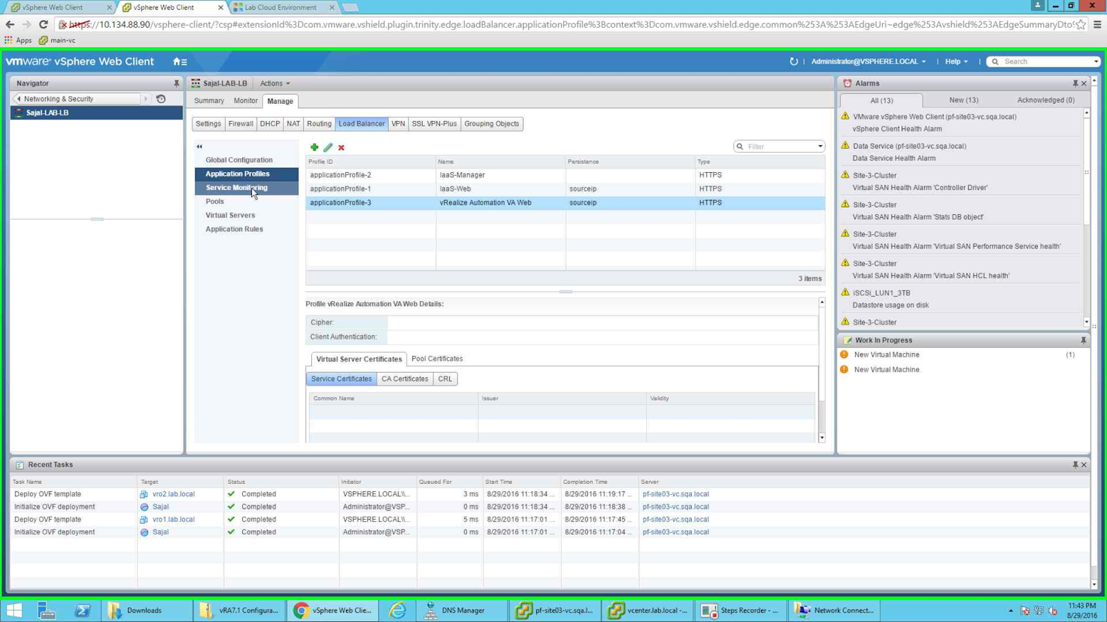
After all three of profiles are configured, the page should look like the following:
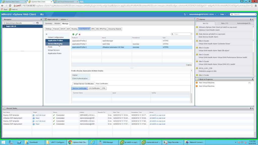 |
| All the three Application Profiles configured |
Next we need to configure Service Monitoring. This will enable LB to learn the status of the members (whether they are UP or DOWN), based on the status the traffic will be routed to the required node. So be very careful while configuring these. I did not notice an extra in a single line and result was my vRA Pool members were down. So no traffic was being routed to the main vRA portal. Once I cross checked the Service Monitoring configuration then I got it corrected. So be careful while configuring these (I know I am repeating this :) ) . Start this configuration by selecting "Service Monitoring" from left tab and clicking the green + sign from the new pane. I will create a total of 3 Service Monitors:
- IaaS Manager
- IaaS Web
- vRealize Automation VA Web
 |
| IaaS Web Configuration |
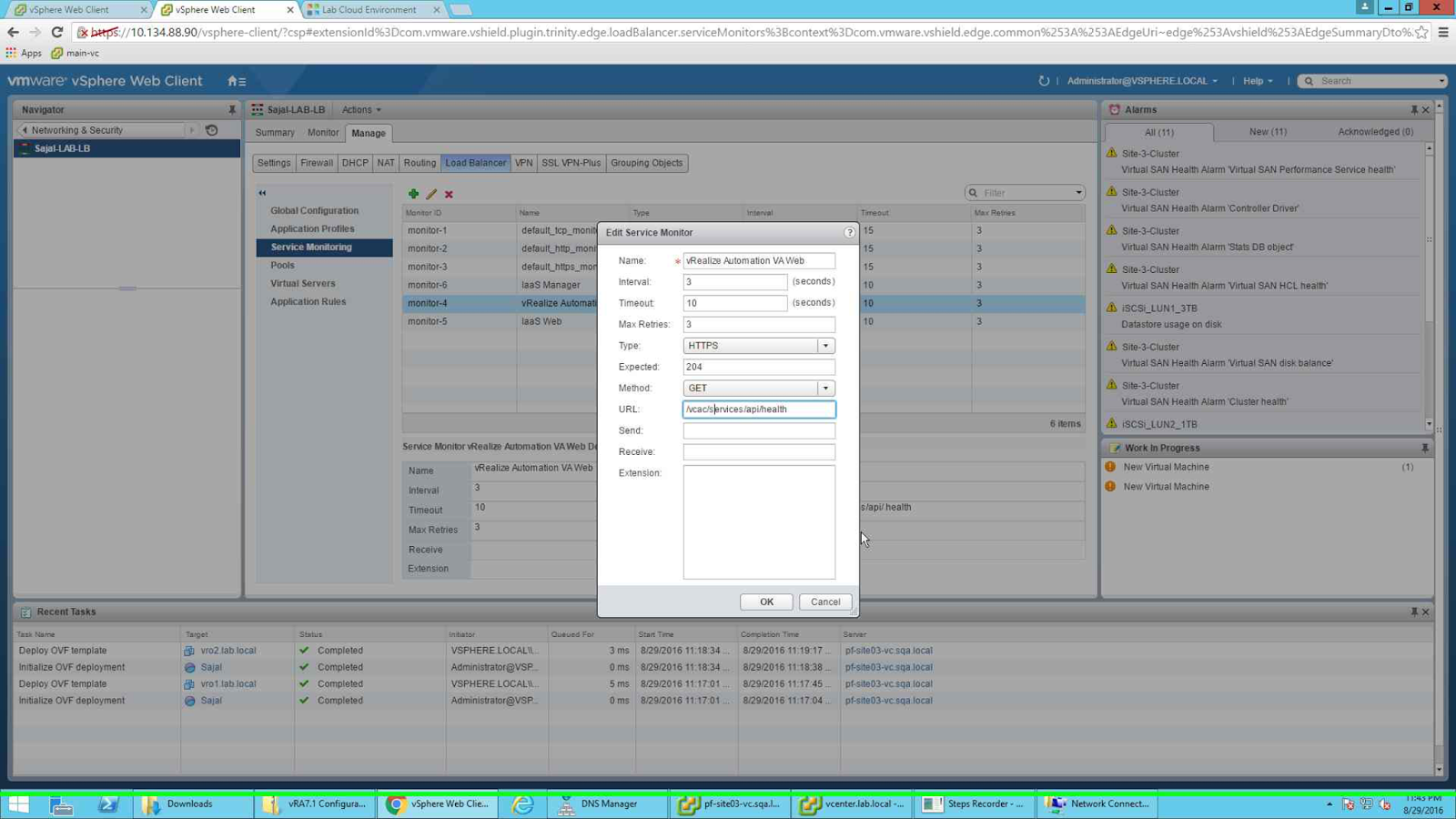
Next one is "vRealize Automation VA Web"
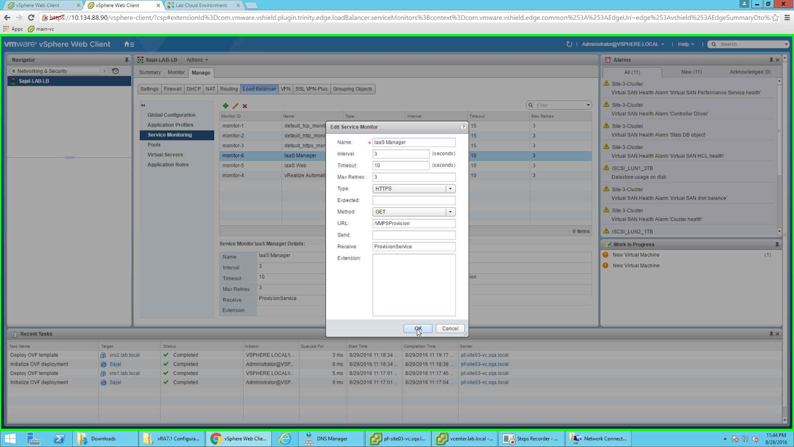
The last one is "IaaS Manager"
 |
| IaaS Manager |
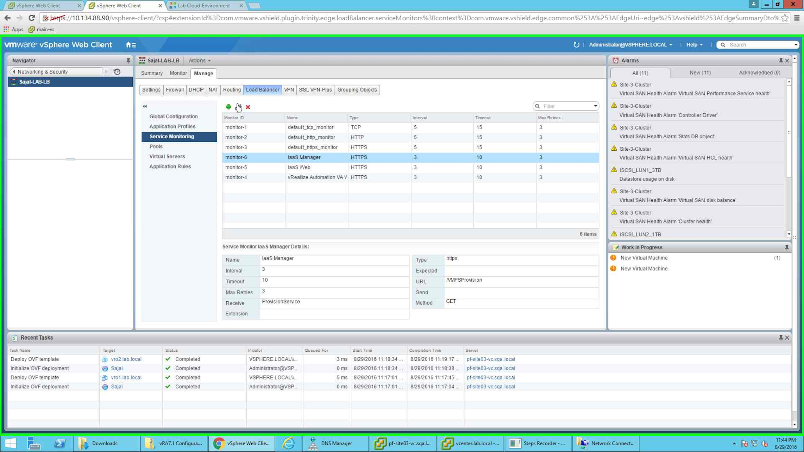
Once all three are configured, the screen should look like the following:
 |
| Service Monitor Screen |
All these service monitors will be tied with the pools that we are going to create in the next step. We need to configure Pools now. We will configure the following 4 pools:
- pool_vra-va-web_443
- pool_vra-rconsole_8444
- pool_iaas-web_443
- pool_iaas-manager_443
Note the pool rconsole, it is for Remote Console. You can omit it if you do not want to provide remote console.
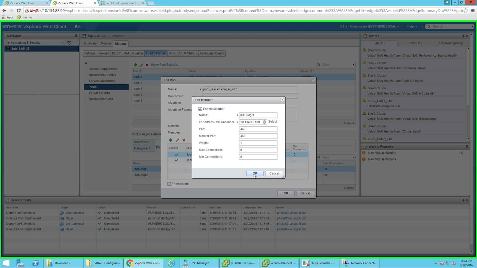
We will start the configuration with the "pool_iaas-manager_443". To configure, first click on the green + button to add new Pool. Give it the name, choose the algorithm as Round Robin. For monitor choose the monitor "IaaS Manager".
Next we will add the Members. Click on the green + button under Members. Provide the node a name, next either provide the IP Address of the node or you can simply select the node as an object. Next we need to provide which port we want to configure for. For this purpose we will select 443 as the port.
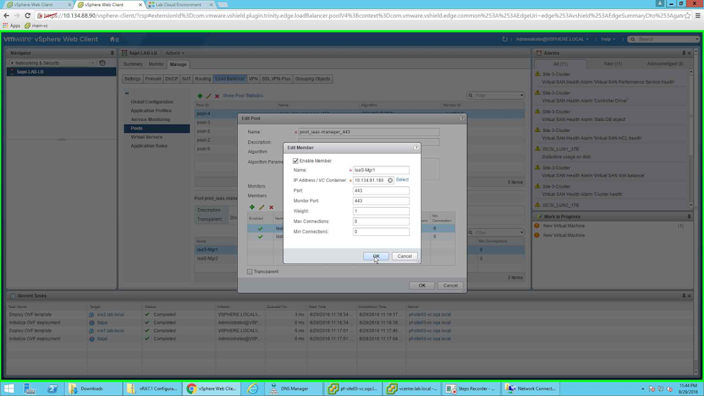 |
| Add first iaas manager node |
Similarly will add IaaS-Mgr2 node as member.
 |
| Add second iaas manager node |
Once both the members are configured then the pool should look like the following:
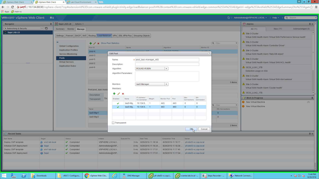 |
| pool_iaas-manager_443 |
Like wise we will configure all the rest of the pools. But note that for remote console i.e, for pool_vra-rconsole_8444, the nodes will have 8444 as the port. So after all the pools are configured, the screen should look like the following:
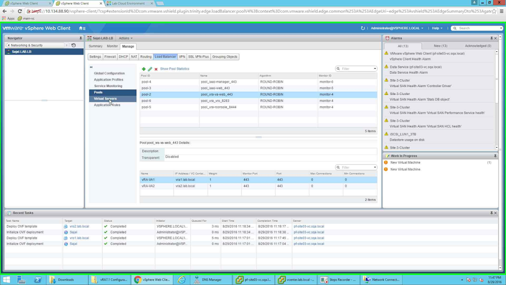 |
| All the pools configured |
For vra remote console pool (pool_vra-rconsole_8444) configuration will be same as pool_vra-va_443, only difference being the port number, in place of 443 it should be 8444.
Next we need to configure the virtual servers. We will configure the following 4 virtual servers:
- vs_iaas-manager_443
- vs_vra-va-web_443
- vs_vra-vr-rconsole_443
- vs_iaas-web_443
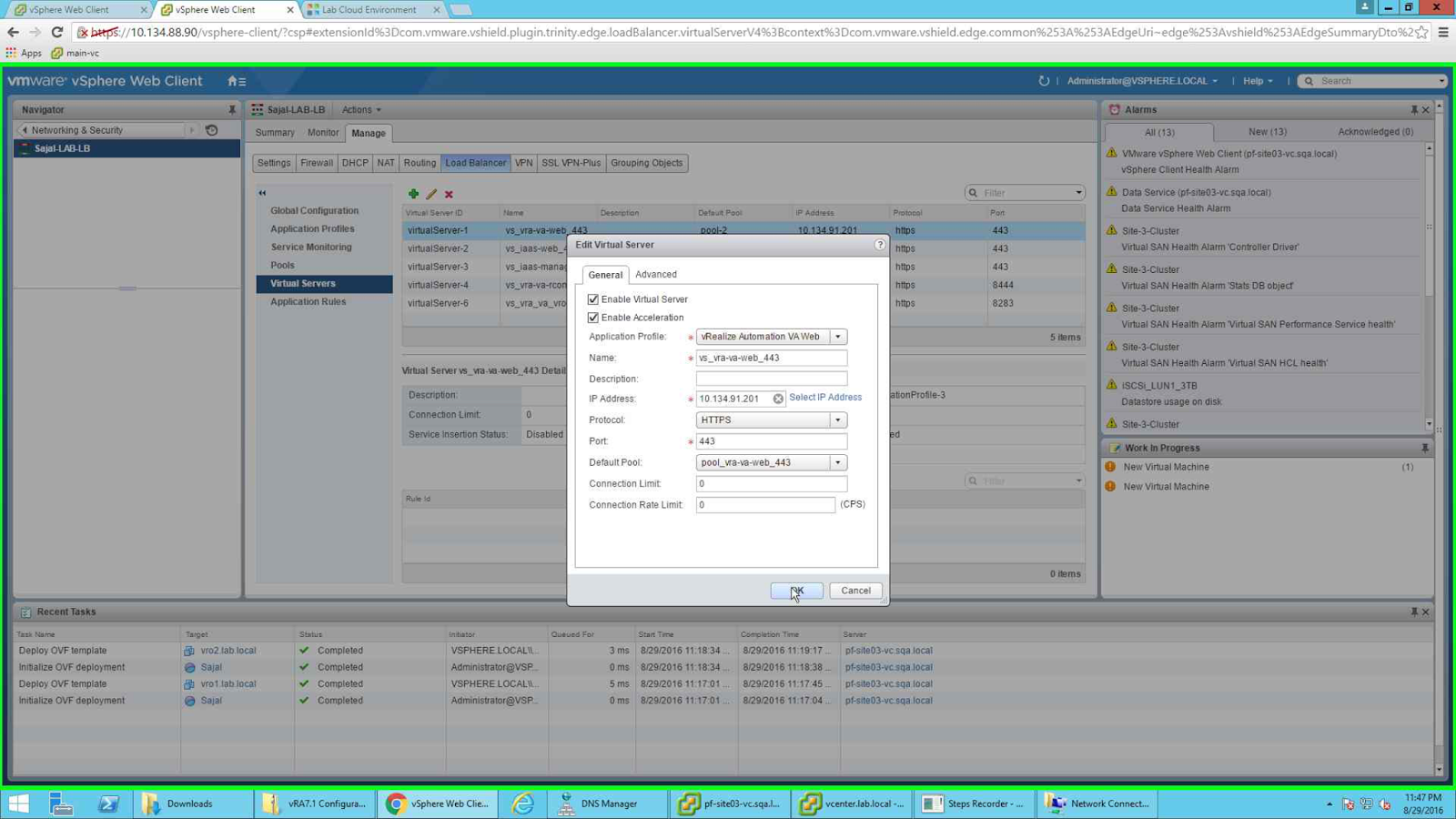
To configure the above, go to Virtual Servers section and click on the green + button to add new virtual server. For each one of them select "Enable Virtual Server" and "Enable Acceleration".
For vs_vra-va-web_443 select application profile as "vRealize Automation VA Web", provide the name, provide the IP address (VIP), select protocol as HTTPS, port number as 443 and the default pool as pool_vra-va-web_443. Once done click on OK to save the configuration.
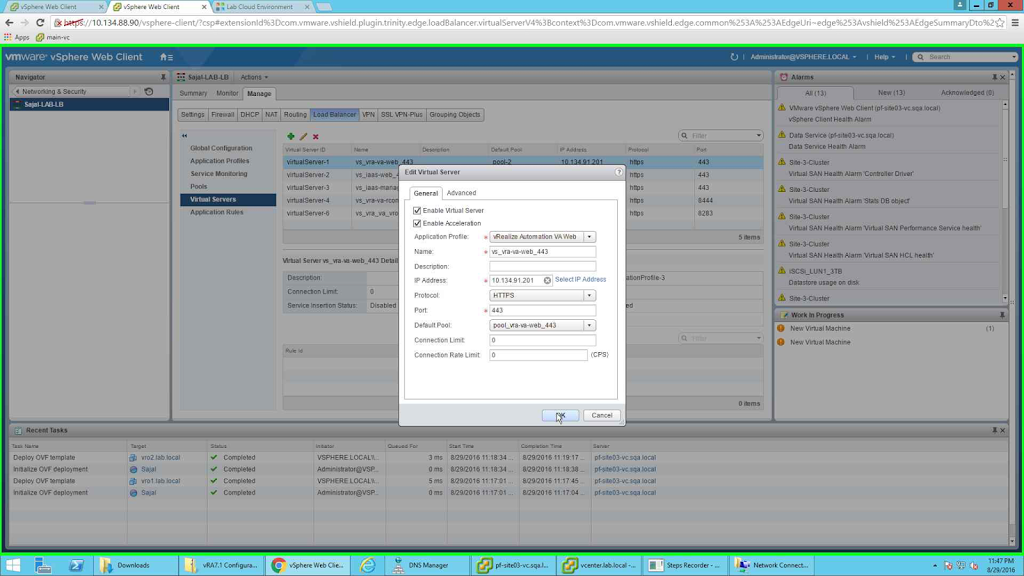 |
| vs_vra-va-web_443 |
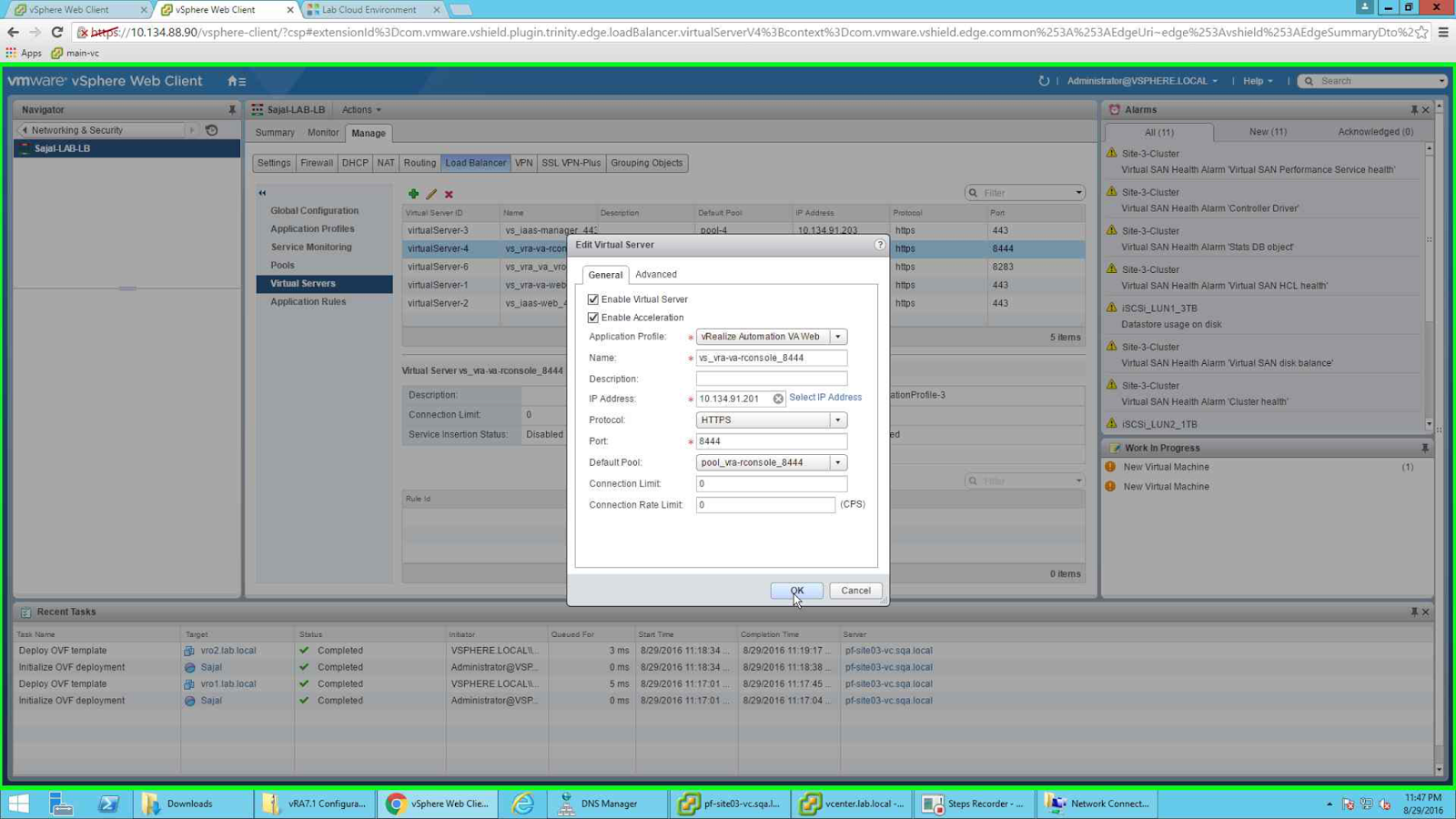
Similarly configure vs_iaas-manager_443 and vs_iaas-web_443 virtual servers. The difference between these pools and vs_vra-vr-rconsole_443 is given in the below screenshot. The port being the only difference.
 |
| vs_vra-va-rconsole_8444 |
Once all the required pools are configured the screen should look like the below screenshot.
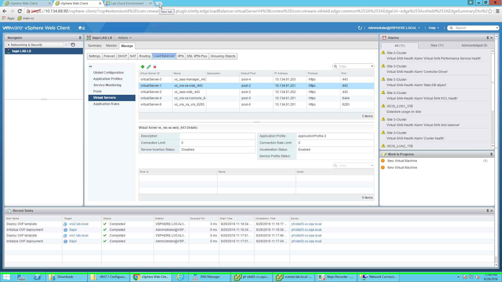 |
| Final screenshot for Virtual Servers |
Now your Load balancer is configured and you are ready to go.
But before proceeding for the vRA installation note the following. If you continue with this configuration, load balancer forwards half of the packets to the second node which is not there before the configuration of the cluster (at the time of deployment you have one active member). So essentially the installation fails.
To have a proper installation, go to pools configuration and select "NONE" as monitors (otherwise pool will show all the members as down, since the services are not up yet and the installation fails). Also disable second member node in all the pools (so half of the packets are not forwarded to the second node).
Once the vRA installation is completed, come back to load balancer and enable all the member nodes of the pool and also set the proper monitors.
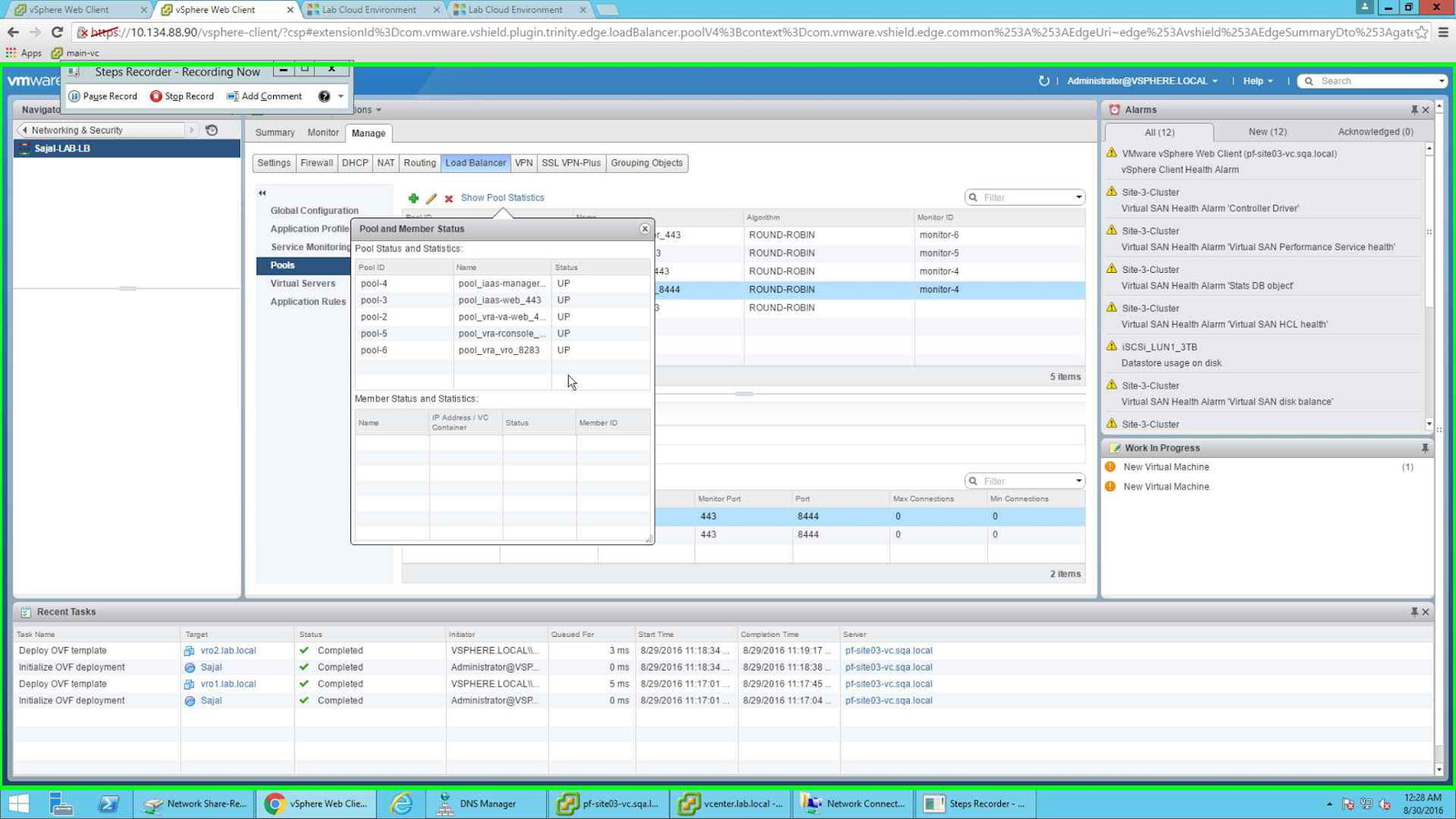
Below is a screenshot for a properly installed environment. You can check the pool status from the below screenshot.
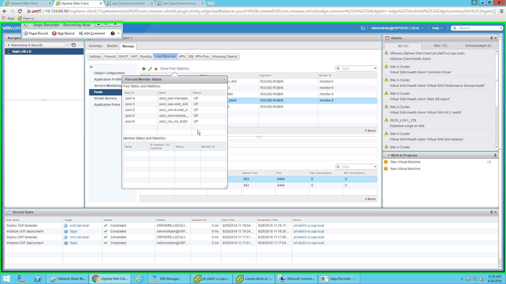 |
| Pool Statistics |
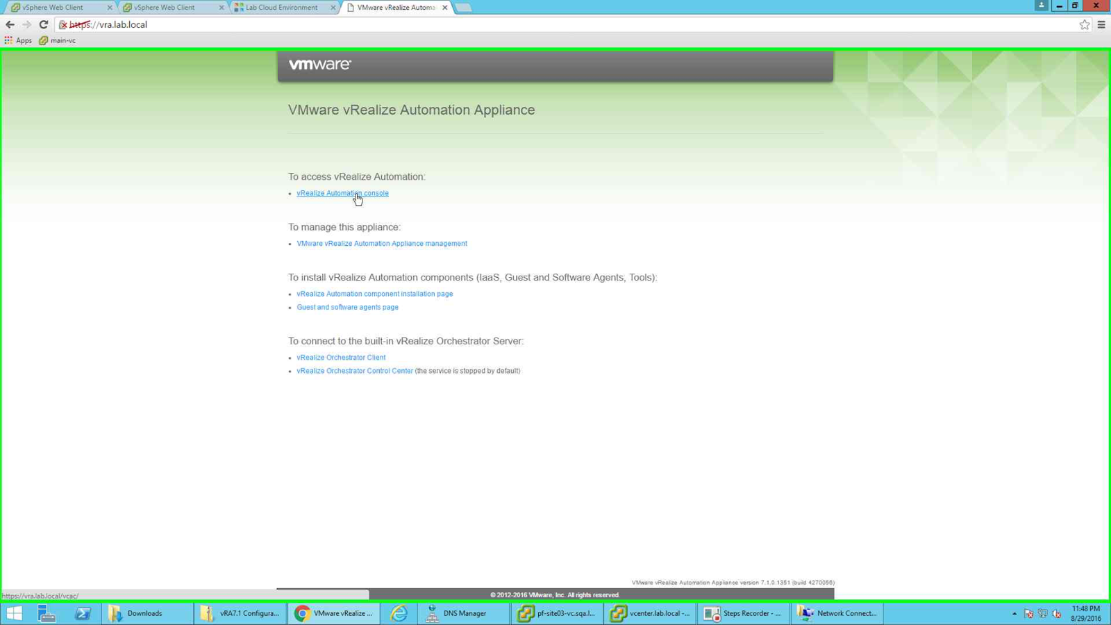
Once the vRA installation completes, you will be able to access it using the vRA url. In my case it is https://vra.lab.local
 |
| main page |
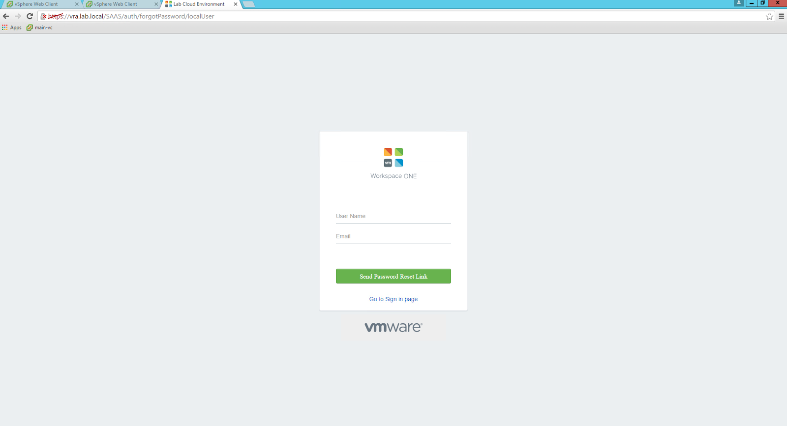
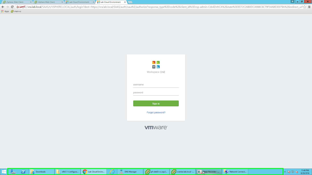 |
| login screen |
Note the login page above. A nice "Forgot Password" link. You can now click on the link to reset your password. This used to show a message "Contact your administrator to reset your password". Now it asks for user name and email id.
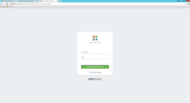 |
| Password reset option |
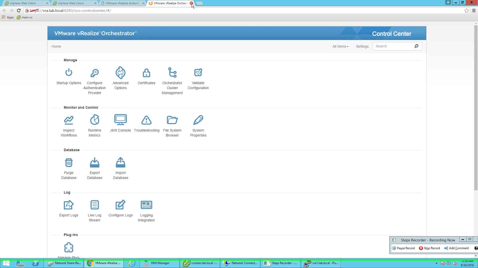
Also remember I configured vRO pool so that I can access and configure the internal vRO server? Below is a screenshot of the same page.
 |
| vRO configuration page |
But to do that you need to enable configurator service in vRA appliance.
Just login to the appliance and run the following command:
# service vco-configurator start
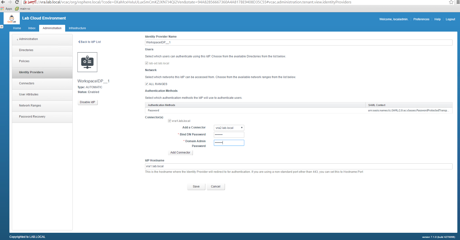
One final point to note, once you configure vRA and configure a Directory for authentication (for example Active Directory) for at least one tenant, you need to configure the identity providers as well.
By default the authentication will happen with one identity provider. We need to change that to load balancer VIP.
First we will add another identity provider (the second node). We can do that by logging to the tenant as Tenant Admin and then Administration--> Identity Provider--> Add provider. Select the second node and then provide the Bind Password and Domain admin password.:
 |
| Add the second identity provider |
Once the above is done then change the IDP hostname to the VIP of the load balancer.
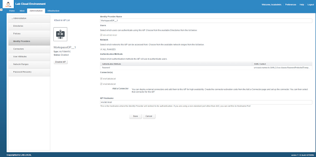 |
| Change the IDP Hostname |
Now you are finally ready to go.
Hope you found this article useful.
Next article is going to be NSX LB configuration for external vRO.
Till then stay tuned.
Do let me know your feedback about the post. What you would like to see me covering etc.